Hello, new member here. My wife and I recently purchased a Hobart A-200. The identification tag was removed at some point, so I can't tell what specific model it is, but it has the brush motor so I know it's pretty old. Now, I'm very mechanically inclined, and I knew going into this thing that it could potentially take quite a bit of work to fix any issues it may have. The price we paid was reasonable enough that I was willing to take the risk.
So, after doing quite a bit of research I decided my course of action would be to go ahead and replace all the bearings and seals, while cleaning the gearbox and planetary and replacing their respective grease. It is currently disassembled in the garage, totally spotless (thanks to 2.5 gallons of degreaser and about eight cans of brake parts cleaner). The other reason I went ahead and completely disassembled it is I'm having it painted before I reassemble. Note - anyone looking for places that can do some really unique colors, and maybe not so expensive as traditional painting businesses, check out your local gun store that does Cerakote-type finishes. Many of them, including the one I am using, will paint/coat just about anything, if no other reason than the challenge of it. I've found many of them are very reasonably priced as well. Here's the link to the color we are going with; I think it will be very cool! https://www.guncandy.com/collections/guncandy-chameleon/products/mako
Anyway, on to my question.
As for the condition of this thing, it ran when my wife picked it up. After going through the transmission and planetary I did find that it appears to have been leaking a small amount of grease. Also, there was a small amount of new grease on the top, where I can tell someone just 'topped it off' as preventative maintenance, but the grease down on the gears was in pretty poor shape. So, I'm glad I decided to go through it after all. Other than that, everything transmission / planetary / bowl lift looks to be in good shape.
I removed the motor, so that I can replace the bearings and so it will be easier to paint. Note - I was unable to find a good write-up on the removal so I just sort of went for it; it was a little sketchy but it ended up okay. One thing I did notice is (forgive me if I call something by the wrong name; I'm an amateur mechanic, not an electrician) the stator windings were covered in grease, which appeared to have come from the gearbox. I don't think there is a seal at the front motor bearing, so I guess it just worked its way into the motor housing. Have any of you seen this?
My other cause for concern is the insulation on the four wires that come from the stator winding was brittle, and when I had to manipulate it while removing the winding there was a lot of cracking noise. I'll need to check the resistance with an ohmmeter before I reinstall; hopefully it tests okay. If it doesn't, it seems I'm limited to a few options. I could find an identical stator winding for this specific mixer on ebay or other sites, or I could try to retrofit a similar motor. Does anyone know of a success story related to that endeavor? The brushes were fairly worn, so I'm replacing those as well. If it all checks out with the ohmmeter I imagine I will heat-shrink some new insulation on those wires and put it back together. However, I know the stator is the likely weak point here so I want to have a plan, in the event I have to replace it.
Thanks for reading!
Cracking noises will come from old insulation literally cracking or glues epoxies and enamels separating. Best bet is to leave windings in place and use WD40 to clean out any tougher oils grease or dirt, wiping it away then leaving it a day. You can splice ends of a winding to increase length for a new connection, just heatshrink the joins. Worst case scenario is chipping the delicate enamel on the windings.
Thanks for the feedback! I noticed the insulation on the winding wires looks like a fabric type insulation that is brittle, either by design or due to the age As long as the wires themselves are not breaking, I'm fine with just heat shrinking the wires, cleaning the windings as best I can without damaging them, and putting it all back together. Here are some photos of the windings. Pretty nasty!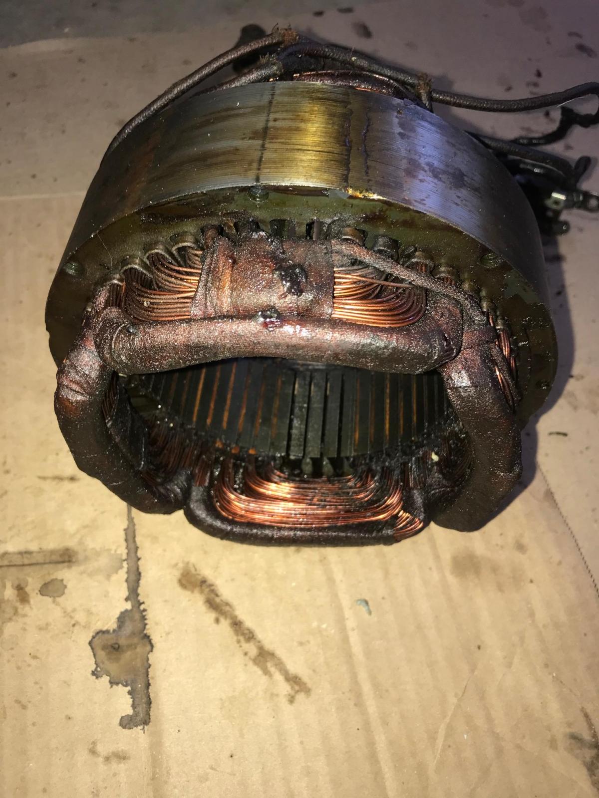
Any amount of dirt here is mostly superficial and actually may help with electrical insulation. The only parts you need to clean are the tracks around which the brushes run, removing deep gouges with a gentle abrasive paper and cleaning with cotton buds and wd40 or a bit of high proof alcohol. Let all chemicals evapourate well. They are not conductive generally but are flammable.
Do not be tempted to use any kind of brush or abrasive on the copper windings themselves. Gentle cotton bud usage only.
Pics of the motor are x-d out.
Camarie, did this one show up? If not, I apologize. Not sure what I'm doing wrong on my end.
Thanks. WOW!!!! The inside of that looks all greasy!! You might need a new one. If so. you might be paying a very expensive price for one!!!! The wiring, also, looks frayed in some spots!!
Maybe you can get a used motor.
Yeah, it's pretty rough. As far as I can tell, the wires aren't actually broken but the insulation is fraying where it broke. I'll check the resistance on the wires and if they check out okay, I'll heat shrink them to keep the insulation from coming apart any more. It did run before I took it apart to do the bearings, clean it out, and get it painted, so here's hoping I've not made matters worse.
The grease is pretty bad in there, isn't it? on the back side it looked like the accumulation of cooking grease (it came from a donut shop). But on the stator winding it sure looks like the same grease that is in the gearcase. I don't recall seeing a seal around the front bearing, and it's sure strange that the grease would work its way back there.
I'll put it back in and hope for the best, but I'm keeping an eye on replacement ones as a contingency plan. You're right - around $300 on ebay for the ones that look to be in really good shape. I imagine they are pretty tough to find, too. Even if it does work now, I almost want to go ahead and buy one when I get a chance, since I suspect I might need one in the future and they aren't going to get any less hard to find.
Looks pretty bad. I hope that you can get it fixed without having to buy another one!!
Yeah, I weighed my options over the past day or so, and happened across a used stator winding on eBay, which I ended up buying for $80. Supposed to have come from a working unit, and it looks pretty much perfect. Of course there could be issued, but it was priced considerably less than the few other ones I had found. I imagine I will put this one in (after I check it's resistance of course), and hang on to the old one. If I could find an electric shop that could clean it up and maybe replace the four wires for a decent price, it would probably be worth keeping since there aren't many of them out there.
Now, my question is - how did the stator windings get full of grease? Like I said, I know there isn't a seal between the motor and transmission, but physics should keep the grease from creeping back into the motor housing. I wonder if either the gear case was overfilled at one point, or if maybe the machine was laid on its back and the grease just seeped back there. Who knows.
Anyway, the whole machine (disassembled) was dropped off yesterday to get painted. I went ahead and ordered all new machine screws to replace the ones that are visible, since some were not the right head shape and all of them up were marred up pretty bad. I think this should come together well!
Some reflections about your mixer:
Now, my question is - how did the stator windings get full of grease? Like I said, I know there isn't a seal between the motor and transmission, but physics should keep the grease from creeping back into the motor housing.
I don't exactly know all US made A200 variations, but for the european production the rotor shaft was always provided with a grease deflector (= kind of small turbine which repulses the grease when the motor rotates). Of course this device has its own limits, especially when the grease is old and losses its emulsion making significant oil drops .
Be that as it may, minor grease/oil splashes over a stator isn't usually a real concern, many motors can bear with it.
All this could be gently cleaned using a soft solvent (isopropanol) and then respecting a very large period of drying (several days). However I feel cautious with such an old motor because it's has wooden stops and fabric insulations, both materials which become durably filled with any kind of subsances... and a stator shloud never be powered if water or solvent residues are remaining into it.
Yeah, I weighed my options over the past day or so, and happened across a used stator winding on eBay, which I ended up buying for $80. Supposed to have come from a working unit, and it looks pretty much perfect.
Sorry for posting too late in this discussion, but my best suggestion consists in entrusting this stator to a motor rewinding shop. Here it would be correctly degreased, dried and inspected.
As per your photos, the stator windings look good, only the main connections are definitively ruined and very hazardous (high risk of electric shock / short-circuit). But luckily, a motor shop can also do this ... they are equiped and skilled to undo any winding head, replace the worn power wires, and then close all this using the right insulating materials and varnish. This operation is likely economical.
Hobart produced the A200 by many decades (and it's still made in the european plants!), you must have in mind that there are many many motor variations, and they parts are not as easily interchangeable as they look. For this kind of servicing, I personally always preferred the solution which preserves the original factory paired parts.
I think youd be hard pressed to find someone to rewind a motor for a reasonable price. Pattern is critical which makes it time consuming and fiddly. One scratch and you have to start again.
Just clean it best you can but dont touch the copper. Get the soldering iron out and replace the wires connecting yourself with suitable high current wires.
Take this from me, electrical engineer with 15 years of electrical repairs.
Motors and grinding metal get hot which will vapourise and circulate grease, metal shards, residual flour and all things into places you wouldnt expect. Its a long time to get like that, so dont worry.
This is actually not that bad for such an old and well used piece of equipment.
I think youd be hard pressed to find someone to rewind a motor for a reasonable price. Pattern is critical which makes it time consuming and fiddly. One scratch and you have to start again.
For this motor I didn't advise to get the whole stator rewound (since it's looks good as you said), but only to redo it's power wires "by the rulebook" (that is opening the winding's head and solder new wires on the winding ends, and then to close all this using modern and efficient insulation sheath and varnishes).
My small rewind shop charges this task for 25 euros in france, a country where human labour is very costly because of high tax-rates ; but I don't estimate this is a so expensive service. I'm sure the craftsmans are more skilled in the US since you have a much more variety of motors, especially single-phase fractionnal HP like in the A200 (here 90% are 3-phase)
Ah, gotcha! Yes 25 euros for some rewiring is a reasonable price. Not really fair to expect it for less :p Electrical repair can be a slow and humble trade in this consumer world.
I make the assumption that as matey not only has the cover off but has the motor in bits, he probably owns a soldering iron :)
Thank you both for your input! Yes, I do have a soldering iron - electrical isn't my strongest subject but I can get through the basics. Taking a closer look at the winding that was on this unit - wow the four wires coming off it are in terrible shape! It was "repaired" at one point apparently, as the ends are wrapped in electrical tape. By the time you get to the switch several strands are broken on each wire. Shoddy electrical work for sure.
I believe the winding I have coming to me will be in very good shape. If it isn't, where are several electrical shops nearby that repair this sort of stuff so that will be the contingency plan. The last of the replacement parts should arrive this week, and then I will be ready to reassemble as soon as everything is back from getting painted.
It's strange - normally the projects I commit this much time, money, effort, research, and planning into have at least four wheels and an internal combustion engine LOL! But this is going to be a very cool project when it's done and the wife certainly deserves it!
Let us know how it goes!
I'm going to hazard a guess that the three extra wires have something to do with the fact that this particular model does not have a start capacitor.
So, six of the seven wires were labeled with a metal tag. Four gray and three yellow. I'll use a '?' in place of the unknown number of the yellow wire. Here's what I found checking resistance:
3G - 4G 3.1 (ohms)
2G - 1G 3.1
1Y - 5Y 8.4
2G - ?Y .8
1G - ?Y 3.1
(side note - I'm working with a cheap multimeter that I can't calibrate to zero the resistance. When I touch the probes together it reads .8, so we'll assume there's no resistance between 2G and ?Y.)
Looking at how the original 4 wire stator winding was connected to the on/off switch, it seems that 3G and 2G would go on one side, and 4G and 1G would go on the other. That leaves me 1Y, 5Y, and ?Y. Since I don't have whatever component those would have connected to, can they be secured and left unhooked? Or is that too far in wistful thinking?
You mentioned your electrical background; can you tell me what I've done here? LOL...the stator winding that I bought on ebay came today. It looks good, but it has seven wires coming from it, while the one that came off of my mixer has 4.
Thanks!
Hello, could you please post larger pictures of this stator ? A top closer view would be appreciated because it's important to see how many coils there are ... and how they are arranged within the core grooves in order to determine the winding pattern.
How many grooves does have this stator ? Thanks
flormont,
I'm going to do these one at a time because I think they're too large to do together. I will say, after doing some research yesterday I'm pretty sure I determined this stator winding has both a start and a run winding, and so it is supposed to be paired with an electronic start switch and capacitor, as well as a different rotor. If that isn't the case, please correct me LOL this has been a task trying to decipher all the different variations of this mixer.
Yesterday I closely inspected the stator winding that came with the mixer and I found that although the four leads looked really bad, since the brittle insulation was cracked in numerous places, all of the wire strands appeared to be intact until you reach the end of the wire, where it was spliced at one time. I cut the ends of the leads down to about 3" from the body of the stator (keeping track of which wire as which of course), slipped some heat shrink tubing down as far as I could get it, and (while using a piece of cardboard as a heat shield for the coils) heat-shrunk the remaining sections of the leads to cover the cracks in the insulation as well as prevent further problems. Then I soldered in new 12AWG wire and new connections to the on/off switch. The resistance showed the same across the two pairs - 3.0 Ohms (I may have mentioned before - I'm using a really cheesy multimeter that shows .8 Ohms when the leads are shorted to each other, for what its worth).
Anyway, I'm pretty confident my existing stator winding will work just fine. Of course, since I bought the newer one I would be interested in using it, but my understanding is it won't interplay with the older configuration I have. If that is the case, I'm sure I can find someone who wheels and deals in Hobart parts to either buy or trade.
Second photo
And third
Thanks for the pictures.
Here we have a 4-pole split phase stator, which is usually powered with 3 (fixed direction of spin) or 4 leads (both directions of spin possible). The other extra-leads may be overheat built-in protections, or connections of center-tapped coils used for the A200S variation which provides a stirr-speed ... but this is not logical according to your resistance measurements.
Anyway, as you anticipated it, you will not be able to use this stator in replacement of the original one in your repulsion-induction motor. Sorry !
As per the service manual, your original stator should have only 2 pairs of coils, each one rating 2 ohms.
Thanks for the information! No worries, I'm not too concerned about the stator I have now, and I'm sure I can sell the one I bought. I paid $100 shipped, and judging from the prices on similar Hobart stators I think I have a pretty good shot at making that money back.
Well, good luck for your final restoration :)
If your stator fails, please consider the solution of getting it rewind. If you take a look at your first pictures, you'll notice that such a stator has a very basic design with only 4 simple et identical coils to make ... this should be done at a much cheaper price than a split-phase stator .. maybe less then $100 you paid for the wrong replacement stator !
The A200 has been made for many decades, you can't imagine how many different motors fitted it ! And if you also consider the EU-motors locally made for the european market, then you go crazy ! And since the A200 is still manufactured here, the list is still growing : the previous major supplier was Tyco (formely Brook-Crompton Small Motors) but this company ceased its motor production activity, so another supplier replaced it (but I don't know its name).
Given that the A200's case can't be fitted with a standard form-factor motor, a custom motor must be made by equipment manufacturers in a variable-time partnership with Hobart.
Wow! Yes, if my stator fails I will get it rewound. There are a few electrical repair shops in a near town that can do it. Here's how it turned out after I fixed the leads and cleaned it with a soft nylon brush (no cleaning solution) just to get the debris (dead bugs) out.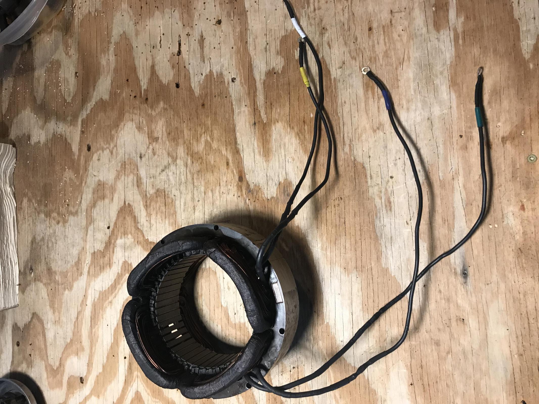
For those who were following this and are interested in seeing the final product, here's an update. I am still waiting on the painter to finish. Instead of going with a powder coat, I'm using a local gunsmith who also does extremely durable firearms coatings, and the type of paint he's using is similar to Cerakote. He's doing it at a significant discount, and mostly in his spare time, so I'm not going to rush him. He was really interested in doing the mixer, since it might open up a new customer base for him. I did check in with him last week, and he said when he started stripping it he noticed the cast iron has a material on the surface that makes it smooth, and he was concerned that sandblasting it would remove that coating as well. So, he's stripping the entire thing by hand, which is what is taking so long.
So, no new developments except I have had my stator winding inspected by an electric shop, and it checked out just fine. I did replace the key on the worm wheel shaft, as I noticed the old one was starting to twist and would eventually break. Turns out in my particular model, that was a designed weak point so that if the mixer was overloaded, the key would break instead of something more costly.
Everything is spotless, inspected, and ready for reassembly. Hopefully I'll be posting photos soon! Thank you for your help!
Did you have any problems with getting the electric shop to check out the stator winding? I thought it would be hard to get them to look at consumer electric motors.
No problem at all. It is a local 'mom and pop' type business, which works on just about everything from consumer products to industrial. I had the stator winding out already so I just stopped by and asked if they could check it out. In fact, I brought both mine and the other one I purchased, which I mistakenly thought could be a back-up for mine. He checked them both in just a few minutes, and the resistance and continuity checked out fine. I believe that's about all he could do with it out of the machine; if I experience any problems once I reassemble then I can bring it to him and he'll test the whole system.